Notes - The Network Layer
The following notes have been made with reference to the book Computer Networking A Top Down Approach by Kurose and Ross. Content has been quoted from the book. All credits to the author.
The transport layer provides various forms of process-to-process communication by relying on the network layer’s host-to-host communication service. It does so without any knowledge about how the network layer actually implements this service.
Unlike the transport and application layers, there is a piece of the network layer in each and every host and router in the network.
An important distinction to keep in mind between the forwarding and routing functions of the network layer.
- Forwarding involves the transfer of a packet from an incoming link to an outgoing link within a single router.
- Routing involves all of a network’s routers, whose collective interactions via routing protocols determine the paths that packets take on their trips from source to destination node.
Introduction
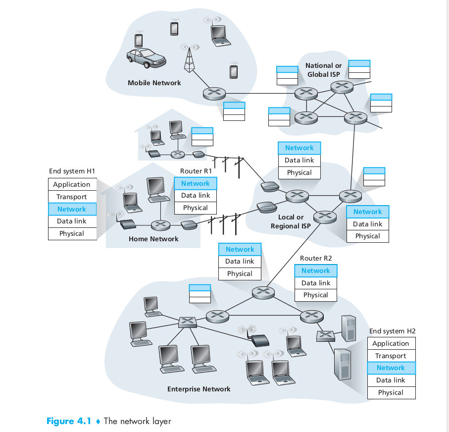
- Two hosts H1 & H2 and suppose H1 is sending information to H2.
- The network layer in H1 takes segments from the transport layer in H1, encapsulates each segment into a datagram (that is, a network-layer packet), and then sends the datagrams to its nearby router, R1.
- At the receiving host, H2, the network layer receives the datagrams from its nearby router R2, extracts the transport-layer segments, and delivers the segments up to the transport layer at H2.
- The primary role of the routers is to forward datagrams from input links to output links.
- Note: The routers in Figure 4.1 are shown with a truncated protocol stack, that is, with no upper layers above the network layer, because (except for control purposes) routers do not run application and transport-layer protocols.
Forwarding and Routing
- The role of the network layer is thus deceptively simple—to move packets from a sending host to a receiving host. To do so, two important network-layer functions can be identified:
- Forwarding: When a packet arrives at a router’s input link, the router must move the packet to the appropriate output link.
- Routing: The network layer must determine the route or path taken by packets as they flow from a sender to a receiver. The algorithms that calculate these paths are referred to as routing algorithms.
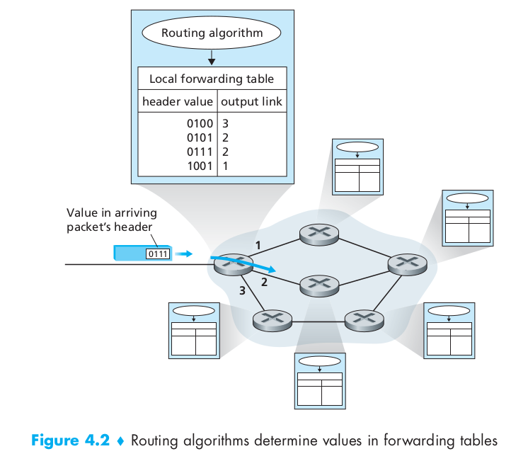
- Every router has a forwarding table.
- A router forwards a packet by examining the value of a field in the arriving packet’s header, and then using this header value to index into the router’s forwarding table.
- The value stored in the forwarding table entry for that header indicates the router’s outgoing link interface to which that packet is to be forwarded.
- Depending on the network-layer protocol, the header value could be the destination address of the packet or an indication of the connection to which the packet belongs.
- The routing algorithm determines the values that are inserted into the routers’ forwarding tables.
- The routing algorithm may be:
- Centralized (e.g., with an algorithm executing on a central site and downloading routing information to each of the routers)
- Decentralized (i.e., with a piece of the distributed routing algorithm running in each router)
In either case, a router receives routing protocol messages, which are used to configure its forwarding table.
- Some other terms:
- Packet switch: a general packet-switching device that transfers a packet from input link interface to output link interface, according to the value in a field in the header of the packet.
- Some packet switches, called link-layer switches, base their forwarding decision on values in the fields of the link-layer frame; switches are thus referred to as link-layer (layer 2) devices.
- Other packet switches, called routers, base their forwarding decision on the value in the network-layer field. Routers are thus network-layer (layer 3) devices, but must also implement layer 2 protocols as well, since layer 3 devices require the services of layer 2 to implement their (layer 3) functionality.
- Other than forwarding and routing, in some computer networks there is a third important funtion called connection setup
- Some network layer architectures—for example, ATM, frame relay, and MPLS ––require the routers along the chosen path from source to destination to handshake with each other in order to set up state before network-layer data packets within a given source-to-destination connection can begin to flow. In the network layer, this process is referred to as connection setup.
Virtual Circuit and Datagram Networks
- Like the transport layer, the network layer can provide connectionless service or connection service between two hosts.
- A network-layer connection service begins with handshaking between the source and destination hosts; and a network-layer connectionless service does not have any handshaking preliminaries.
- Although there are parallels with the transport layer connection-oriented and connectionless services, there are crucial differences:
- In network layer, services are host-to-host services provided by the network layer for the transport layer. In the transport layer the services are process-to-process services provided by the transport layer for the application layer.
- In all major computer network architectures to date (Internet, ATM, frame relay, and so on), the network layer provides either a host-to-host connectionless service or a host-to-host connection service, but not both. Computer networks that provide only a connection service at the network layer are called virtual-circuit (VC) networks; computer networks that provide only a connectionless service at the network layer are called datagram networks.
- The implementation of connection-oriented service in the transport layer and connection service in the network layer are different. Transport layer connection-oriented service is implemented at the edge of the network in the end systems; network layer connection service is implemented in the routers in the network core as well as in the end systems.
Virtual-Circuit Networks
- While the Internet is a datagram network, many alternative network architectures including those of ATM and frame relay are virtual-circuit networks and, therefore, use connections at the network layer.
- These network-layer connections are called virtual circuits (VCs).
- A VC consists of:
- a path (that is, a series of links and routers) between the source and destination hosts
- VC numbers, one number for each link along the path
- entries in the forwarding table in each router along the path
- A packet belonging to a virtual circuit will carry a VC number in its header. Because a virtual circuit may have a different VC number on each link, each intervening router must replace the VC number of each traversing packet with a new VC number. The new VC number is obtained from the forwarding table.
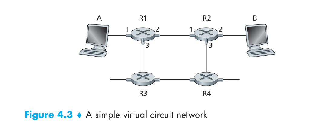
To illustrate the concept, consider the network shown in Figure 4.3. The numbers next to the links of R1 in Figure 4.3 are the link interface numbers. Suppose now that Host A requests that the network establish a VC between itself and Host B. Suppose also that the network chooses the path A-R1-R2-B and assigns VC numbers 12, 22, and 32 to the three links in this path for this virtual circuit. In this case, when a packet in this VC leaves Host A, the value in the VC number field in the packet header is 12; when it leaves R1, the value is 22; and when it leaves R2, the value is 32.
For a VC network, each router’s forwarding table includes VC number translation; for example, the forwarding table in R1 might look something like this:
- Why have different VC number for each link along the path?
- First, replacing the number from link to link reduces the length of the VC field in the packet header.
- Second, and more importantly, VC setup is considerably simplified by permitting a different VC number at each link along the path of the VC. If a common VC number were required for all links along the path, the routers would have to exchange and process a substantial number of messages to agree on a common VC number (e.g., one that is not being used by any other existing VC at these routers) to be used for a connection.
In a VC network, the network’s routers must maintain connection state information for the ongoing connections. Specifically, each time a new connection is established across a router, a new connection entry must be added to the router’s forwarding table; and each time a connection is released, an entry must be removed from the table.
- There are three identifiable phases in a virtual circuit:
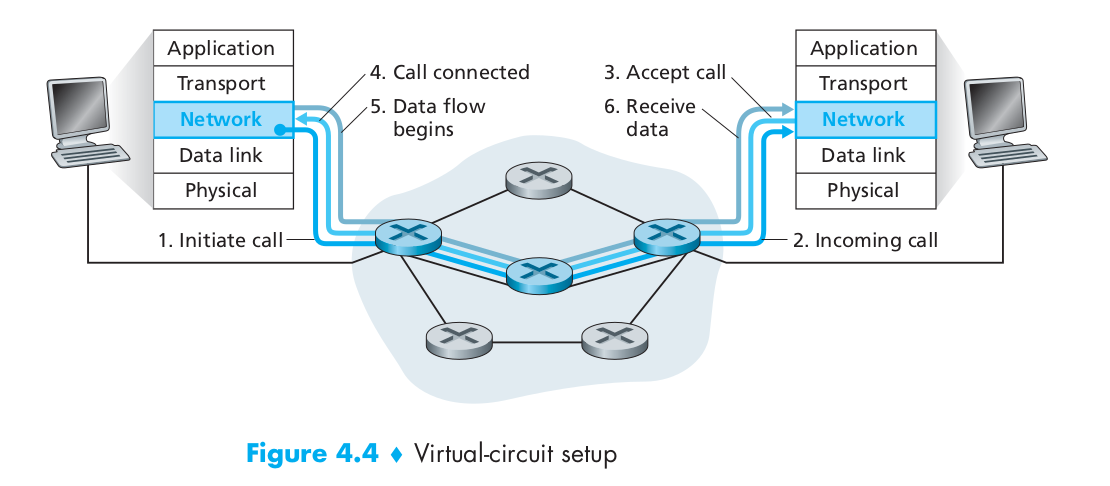
- VC setup: During the setup phase, the sending transport layer contacts the network layer, specifies the receiver’s address, and waits for the network to set up the VC. The network layer determines the path between sender and receiver, that is, the series of links and routers through which all packets of the VC will travel. The network layer also determines the VC number for each link along the path. Finally, the network layer adds an entry in the forwarding table in each router along the path. During VC setup, the network layer may also reserve resources (for example, bandwidth) along the path of the VC.
- Data transfer: As shown in Figure 4.4, once the VC has been established, packets can begin to flow along the VC.
- VC teardown: This is initiated when the sender (or receiver) informs the network layer of its desire to terminate the VC. The network layer will then typically inform the end system on the other side of the network of the call termination and update the forwarding tables in each of the packet routers on the path to indicate that the VC no longer exists.
- The messages that the end systems send into the network to initiate or terminate a VC, and the messages passed between the routers to set up the VC (that is, to modify connection state in router tables) are known as signaling messages, and the protocols used to exchange these messages are often referred to as signaling protocols.
Datagram Networks
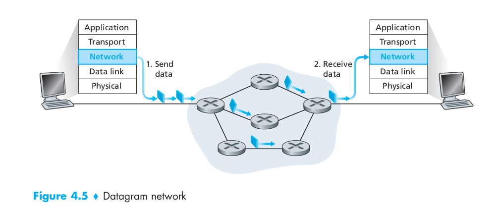
- In a datagram network, each time an end system wants to send a packet, it stamps the packet with the address of the destination end system and then pops the packet into the network.
- As a packet is transmitted from source to destination, it passes through a series of routers. Each of these routers uses the packet’s destination address to forward the packet.
- Specifically, each router has a forwarding table that maps destination addresses to link interfaces; when a packet arrives at the router, the router uses the packet’s destination address to look up the appropriate output link interface in the forwarding table. The router then intentionally forwards the packet to that output link interface.
- To get some further insight into the lookup operation, let’s look at a specific example.
- Suppose that all destination addresses are 32 bits.
- A brute-force implementation of the forwarding table would have one entry for every possible destination address. Since there are more than 4 billion possible addresses, this option is totally out of the question.
- Now let’s further suppose that our router has four links, numbered 0 through 3, and that packets are to be forwarded to the link interfaces as follows:
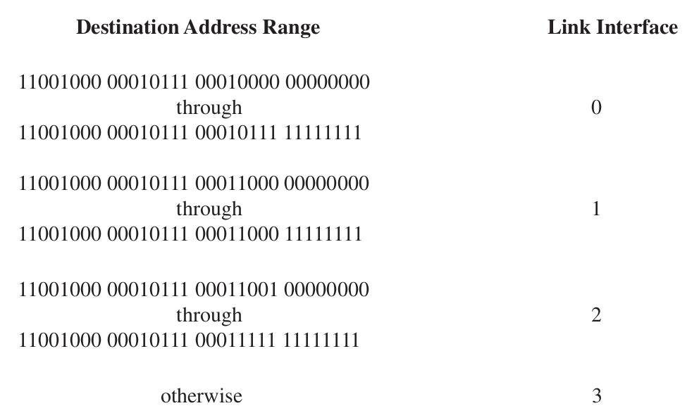
- We could, for example, have the following forwarding table with just four entries:

- With this style of forwarding table, the router matches a prefix of the packet’s destination address with the entries in the table; if there’s a match, the router forwards the packet to a link associated with the match.
- When there are multiple matches, the router uses the longest prefix matching rule; that is, it finds the longest matching entry in the table and forwards the packet to the link interface associated with the longest prefix match.
What’s inside a Router?
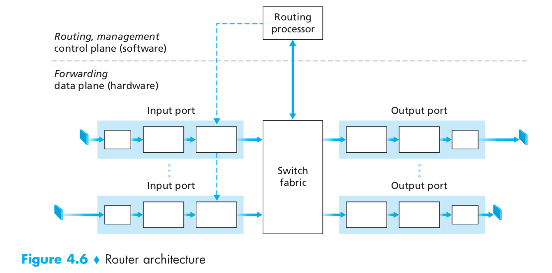
- A high-level view of a generic router architecture is shown in Figure 4.6. Four router components can be identified:
- Input ports:
- An input port performs several key functions.
- It performs the physical layer function of terminating an incoming physical link at a router
- An input port also performs link-layer functions needed to interoperate with the link layer at the other side of the incoming link
- Perhaps most crucially, the lookup function is also performed at the input port. It is here that the forwarding table is consulted to determine the router output port to which an arriving packet will be forwarded via the switching fabric.
- Control packets (for example, packets carrying routing protocol information) are forwarded from an input port to the routing processor.
- Note that the term port here refers to the physical input and output router interfaces
- An input port performs several key functions.
- Switching fabric
- The switching fabric connects the router’s input ports to its output ports. This switching fabric is completely contained within the router—a network inside of a network router!
- Output ports
- An output port stores packets received from the switching fabric and transmits these packets on the outgoing link by performing the necessary link-layer and physical-layer functions.
- Routing processor
- The routing processor executes the routing protocols, maintains routing tables and attached link state information, and computes the forwarding table for the router. It also performs some network management functions.
- Input ports:
- A router’s input ports, output ports, and switching fabric together implement the forwarding function and are almost always implemented in hardware. These forwarding functions are sometimes collectively referred to as the router forwarding plane.
- The router control plane functions are usually implemented in software and execute on the routing processor (typically a traditional CPU).
Input Processing
- A more detailed view of input processing is given in Figure 4.7.
- As discussed above, the input port’s line termination function and link-layer processing implement the physical and link layers for that individual input link.
- The lookup performed in the input port is central to the router’s operation—it is here that the router uses the forwarding table to look up the output port to which an arriving packet will be forwarded via the switching fabric.
- The forwarding table is computed and updated by the routing processor, with a shadow copy typically stored at each input port. The forwarding table is copied from the routing processor to the line cards over a separate bus (e.g., a PCI bus) indicated by the dashed line from the routing processor to the input line cards in Figure 4.6.
- With a shadow copy, forwarding decisions can be made locally, at each input port, without invoking the centralized routing processor on a per-packet basis and thus avoiding a centralized processing bottleneck.
- Given the existence of a forwarding table, lookup is conceptually simple—we just search through the forwarding table looking for the longest prefix match, lookup must be performed in hardware for speed.
- Once a packet’s output port has been determined via the lookup, the packet can be sent into the switching fabric. In some designs, a packet may be temporarily blocked from entering the switching fabric if packets from other input ports are currently using the fabric. A blocked packet will be queued at the input port and then scheduled to cross the fabric at a later point in time.
- Although “lookup” is arguably the most important action in input port processing, many other actions must be taken:
- physical and link-layer processing must occur, as discussed above
- the packet’s version number, checksum and time-to-live field must be checked and the latter two fields rewritten
- counters used for network management (such as the number of IP datagrams received) must be updated.
Output processing
- Output port processing, shown in Figure 4.9, takes packets that have been stored in the output port’s memory and transmits them over the output link. This includes selecting and de-queueing packets for transmission, and performing the needed link-layer and physical-layer transmission functions.
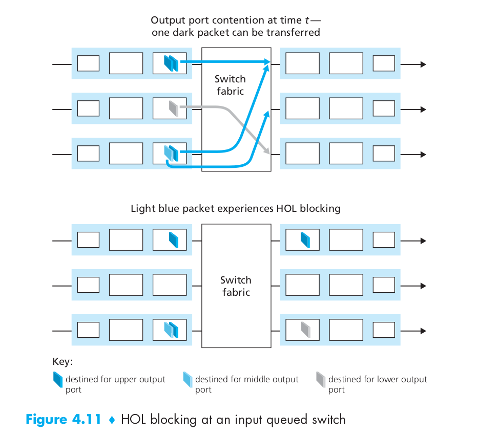
What is Head-of-the-Line (HOL) blocking
- Figure 4.11 shows an example in which two packets (darkly shaded) at the front of their input queues are destined for the same upper-right output port. Suppose that the switch fabric chooses to transfer the packet from the front of the upper-left queue. In this case, the darkly shaded packet in the lower-left queue must wait. But not only must this darkly shaded packet wait, so too must the lightly shaded packet that is queued behind that packet in the lower-left queue, even though there is no contention for the middle-right output port (the destination for the lightly shaded packet). This phenomenon is known as head-of-the-line (HOL) blocking in an input-queued switch.
Reference videos for some topics
| Topic | Video Link |
|---|---|
| IP Datagram Format | https://www.youtube.com/watch?v=AffMzrz96Nc |
| IP Data Fragmentation and Re-Assembly | https://www.youtube.com/watch?v=MmJonsmiwqc |
| Introduction to Computer network and IP address | https://www.youtube.com/watch?v=UXMIxCYZu8o |
| Types of Casting: Unicast, Limited Broadcast, Directed Broadcast | https://www.youtube.com/watch?v=hffYt7RDrgk&t=630s |
| Subnets, Subnet Mask, Routing | https://www.youtube.com/watch?v=3QWrq5gN8VY&t=209s |
| Variable length subnet masking (VLSM) | https://www.youtube.com/watch?v=GJrS5ckgjAs&t=622s |
| Classless Inter Domain Routing (CIDR) | https://www.youtube.com/watch?v=86RDE_bP1Bs&pbjreload=10 |
| Subnetting in CIDR, VLSM in CIDR | https://www.youtube.com/watch?v=zYOgpo0SDBc&pbjreload=10 |
| Some interesting problems on subnet mask | https://www.youtube.com/watch?v=O-8MYVVKpk8 |
Obtaining a Host Address: the Dynamic Host Configuration Protocol (DHCP)
- Once an organization has obtained a block of addresses, it can assign individual IP addresses to the host and router interfaces in its organization. A system administrator will typically manually configure the IP addresses into the router (often remotely, with a network management tool). Host addresses can also be configured manually, but more often this task is now done using the Dynamic Host Configuration Protocol (DHCP).
- DHCP allows a host to obtain (be allocated) an IP address automatically. A network administrator can configure DHCP so that a given host receives the same IP address each time it connects to the network, or a host may be assigned a temporary IP address that will be different each time the host connects to the network.
- In addition to host IP address assignment, DHCP also allows a host to learn additional information, such as its subnet mask, the address of its first-hop router (often called the default gateway), and the address of its local DNS server.
- Because of DHCP’s ability to automate the network-related aspects of connecting a host into a network, it is often referred to as a plug-and-play protocol.
- DHCP is a client-server protocol. A client is typically a newly arriving host wanting to obtain network configuration information, including an IP address for itself.
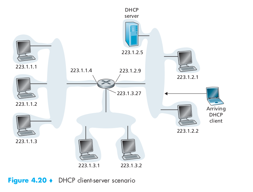
- In the simplest case, each subnet will have a DHCP server. If no server is present on the subnet, a DHCP relay agent (typically a router) that knows the address of a DHCP server for that network is needed. Figure 4.20 shows a DHCP server attached to subnet 223.1.2/24, with the router serving as the relay agent for arriving clients attached to subnets 223.1.1/24 and 223.1.3/24. In our discussion below, we’ll assume that a DHCP server is available on the subnet.
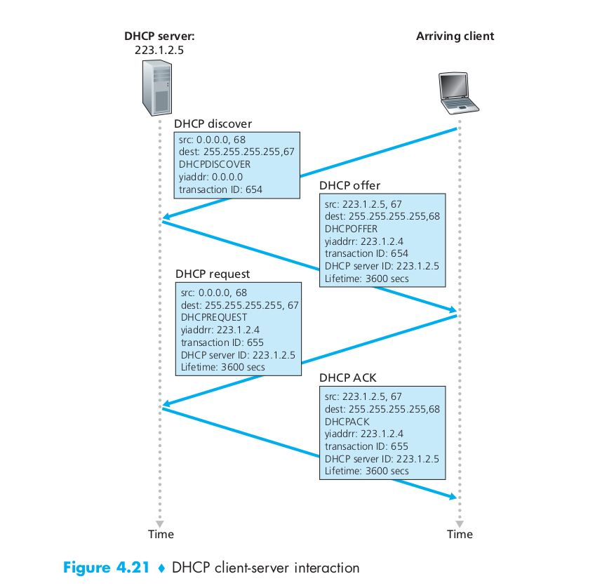
- For a newly arriving host, the DHCP protocol is a four-step process. The four steps are:
- DHCP server discovery
- The first task of a newly arriving host is to find a DHCP server with which to interact. This is done using a DHCP discover message, which a client sends within a UDP packet to port 67. The UDP packet is encapsulated in an IP datagram.
- But to whom should this datagram be sent? The host doesn’t even know the IP address of the network to which it is attaching, much less the address of a DHCP server for this network.
- Given this, the DHCP client creates an IP datagram containing its DHCP discover message along with the broadcast destination IP address of 255.255.255.255 and a “this host” source IP address of 0.0.0.0. The DHCP client passes the IP datagram to the link layer, which then broadcasts this frame to all nodes attached to the subnet.
An interesting read about the
0.0.0.0IP address => https://superuser.com/questions/949428/whats-the-difference-between-127-0-0-1-and-0-0-0-0 - DHCP server offer(s)
- A DHCP server receiving a DHCP discover message responds to the client with a DHCP offer message that is broadcast to all nodes on the subnet, again using the IP broadcast address of 255.255.255.255.
- Since several DHCP servers can be present on the subnet, the client may find itself in the enviable position of being able to choose from among several offers. Each server offer message contains the transaction ID of the received discover message, the proposed IP address for the client, the network mask, and an IP address lease time—the amount of time for which the IP address will be valid. It is common for the server to set the lease time to several hours or days.
- DHCP request
- The newly arriving client will choose from among one or more transmitsserver offers and respond to its selected offer with a DHCP request message, echoing back the configuration parameters.
- DHCP ACK
- The server responds to the DHCP request message with a DHCP ACK message, confirming the requested parameters.
- DHCP server discovery
Once the client receives the DHCP ACK, the interaction is complete and the client can use the DHCP-allocated IP address for the lease duration. Since a client may want to use its address beyond the lease’s expiration, DHCP also provides a mechanism that allows a client to renew its lease on an IP address.
From a mobility aspect, however, DHCP does have shortcomings. Since a new IP address is obtained from DHCP each time a node connects to a new subnet, a TCP connection to a remote application cannot be maintained as a mobile node moves between subnets.
Network Address Translation (NAT)
Reference video - https://youtu.be/_MZbwHyE0Ck
Routing Algorithms
Whether the network layer provides a datagram service (in which case different packets between a given source-destination pair may take different routes) or a VC service (in which case all packets between a given source and destination will take the same path), the network layer must nonetheless determine the path that packets take from senders to receivers. We’ll see that the job of routing is to determine good paths (equivalently, routes), from senders to receivers, through the network of routers.
Typically a host is attached directly to one router, the default router for the host (also called the first-hop router for the host). Whenever a host sends a packet, the packet is transferred to its default router. We refer to the default router of the source host as the source router and the default router of the destination host as the destination router. The problem of routing a packet from source host to destination host clearly boils down to the problem of routing the packet from source router to destination router.
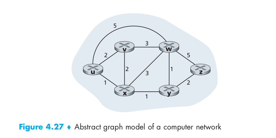
A graph is used to formulate routing problems. Recall that a graph G = (N,E) is a set N of nodes and a collection E of edges, where each edge is a pair of nodes from N. In the context of network-layer routing, the nodes in the graph represent routers—the points at which packet-forwarding decisions are made—and the edges connecting these nodes represent the physical links between these routers. Such a graph abstraction of a computer network is shown in Figure 4.27.
An edge also has a value representing its cost. Typically, an edge’s cost may reflect the physical length of the corresponding link, the link speed, or the monetary cost associated with a link.
- Broadly, one way in which we can classify routing algorithms is according to whether they are global or decentralized.
A global routing algorithm computes the least-cost path between a source and destination using complete, global knowledge about the network. That is, the algorithm takes the connectivity between all nodes and all link costs as inputs. This then requires that the algorithm somehow obtain this information before actually performing the calculation. The calculation itself can be run at one site (a centralized global routing algorithm) or replicated at multiple sites. In practice, algorithms with global state information are often referred to as link-state (LS) algorithms, since the algorithm must be aware of the cost of each link in the network.
In a decentralized routing algorithm, the calculation of the least-cost path is carried out in an iterative, distributed manner. No node has complete information about the costs of all network links. Instead, each node begins with only the knowledge of the costs of its own directly attached links. Then, through an iterative process of calculation and exchange of information with its neighboring nodes (that is, nodes that are at the other end of links to which it itself is attached), a node gradually calculates the least-cost path to a destination or set of destinations. The decentralized routing algorithm we will see is called a distance-vector (DV) algorithm, because each node maintains a vector of estimates of the costs (distances) to all other nodes in the network.
- A second broad way to classify routing algorithms is according to whether they are static or dynamic.
In static routing algorithms, routes change very slowly over time, often as a result of human intervention (for example, a human manually editing a router’s forwarding table).
Dynamic routing algorithms change the routing paths as the network traffic loads or topology change. A dynamic algorithm can be run either periodically or in direct response to topology or link cost changes. While dynamic algorithms are more responsive to network changes, they are also more susceptible to problems such as routing loops and oscillation in routes.
- A third way to classify routing algorithms is according to whether they are load-sensitive or load-insensitive.
In a load-sensitive algorithm, link costs vary dynamically to reflect the current level of congestion in the underlying link. If a high cost is associated with a link that is currently congested, a routing algorithm will tend to choose routes around such a congested link.
Today’s Internet routing algorithms (such as RIP, OSPF, and BGP) are load-insensitive, as a link’s cost does not explicitly reflect its current (or recent past) level of congestion.
The Link-State (LS) Routing Algorithm
- Recall that in a link-state algorithm, the network topology and all link costs are known, that is, available as input to the LS algorithm. In practice this is accomplished by having each node broadcast link-state packets to all other nodes in the network, with each link-state packet containing the identities and costs of its attached links. In practice this is often accomplished by a link-state broadcast algorithm.
- The link-state routing algorithm we present below is known as Dijkstra’s algorithm, named after its inventor.
- Dijkstra’s algorithm computes the least-cost path from one node to all other nodes in the network.
The Distance-Vector (DV) Routing Algorithm
- Whereas the LS algorithm is an algorithm using global information, the distance-vector (DV) algorithm is iterative, asynchronous, and distributed.
- It is distributed in that each node receives some information from one or more of its directly attached neighbors, performs a calculation, and then distributes the results of its calculation back to its neighbors.
- It is iterative in that this process continues on until no more information is exchanged between neighbors (Interestingly, the algorithm is also self-terminating—there is no signal that the computation should stop; it just stops).
- The algorithm is asynchronous in that it does not require all of the nodes to operate in lockstep with each other.
- Bellman-Ford is used to calculate the distances between the nodes.
- DV-like algorithms are used in many routing protocols in practice, including the Internet’s RIP and BGP, ISO IDRP, Novell IPX, and the original ARPAnet.
A Comparison of LS and DV Routing Algorithms
| LS Routing Algorithm | DV Routing Algorithm |
|---|---|
| Each node talks with all other nodes (via broadcast), but it tells them only the costs of its directly connected links. | Each node talks to only its directly connected neighbors, but it provides its neighbors with least-cost estimates from itself to all the nodes (that it knows about) in the network. |
| Each node requires to know the cost of each link in the network. This requires O(N.E) messages to be sent. Also, whenever a link cost changes, the new link cost must be sent to all nodes. | The DV algorithm requires message exchanges between directly connected neighbors at each iteration. The time needed for the algorithm to converge can depend on many factors. When link costs change, the DV algorithm will propagate the results of the changed link cost only if the new link cost results in a changed least-cost path for one of the nodes attached to that link. |
| The implementation of LS is an O(N^2) algorithm requiring O(N.E)) messages. | The DV algorithm can converge slowly and can have routing loops while the algorithm is converging. DV also suffers from the count-to-infinity problem. |
| An LS node is computing only its own forwarding tables; other nodes are performing similar calculations for themselves. This means route calculations are somewhat separated under LS, providing a degree of robustness. | An incorrect node calculation can be diffused through the entire network under DV. |
In the end, neither algorithm is an obvious winner over the other; indeed, both algorithms are used in the Internet.
